UAT wanted to provide a location for UAT students to show off their art skills, to write down project ideas and to provide a board for poetry and various other literary works. The idea was to create a backlit whiteboard. The idea was kicked around UAT until it reached Professor Clarke, who then suggested that instead of just backlighting the board, the board should have LED's that can be individually controlled to be on or off. We ended up using an 8 by 26 array of blue LEDs spaced 6 inches apart, on a 4 feet by 28 feet wall.
Construction
The "wall" is made out of two separate layers. The top most layer is diffused acrylic, which helps diffuse the light. The second layer underneath that is thick sheet of plastic with holes drilled 6 inches apart. This allowed us to put the LED into the hole and glue it down. From there we ran wires between the different LED's to provide one common ground per column, and we ran a common anode per row. This allows us to turn on a single LED by grounding a column and providing a current to a row.
Hardware
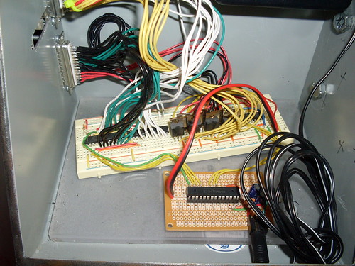
The LED wall is being run off a standard Parallax SX28, some transistors for the rows since they had to provide a massive amount of power, and two MAX6979 to sink the columns. The project was built on top of a breadboard as there was no time or need to create a PCB and have it manufactured specifically for this project.
The MAX6979's are shift registers, this means we provide a clock signal to input the data into the chip at whatever speed we desire (within limits off course). It is an extremely simple serial communication protocol. So we only have to provide a CLK signal, a DIN for data in, a LE which is a latch enable, and OE which is the output enable. Shift registers can easily be chained so that we could control all of the shift registers using just 4 pins on the microcontroller. This serial protocol is extremely stable even in conditions where the clock speed of the microcontroller is constantly changing because of drift (the SX28 is not known for its internal clock correctness).
For row control a demux was used. THis would only require 4 more pins on the microcontroller to control all of the transistors to turn on and off the row of LED's. A binary coded decimal is sent to the demux to select the transistor to turn on.
In total 8 microcontroller pins were used in driving the entire display. This had the added benefit that the rest of the pins on the SX28 could be used for future add-ons to the display.
The following hardware was used:
- Parallax SX28
- Demux
- Transistors
- MAX6979
- 208 blue LEDs

Future
Currently it is running Conway's game of life, and the board provides its function but at the same time it does not allow the students to interact with it in a new and novel way. The original idea that was presented was a serial port that was on the outside that then allowed students to walk up to it and program the LED's to flash various different shapes/patterns/pieces of art.
More pictures
More pictures can be found on my Flickr Whiteboard photo set.